
- RF AMPLIFIER
- RF POWER GENERATOR
- MATCHING BOX
- RF EQUIPMENT
- RF COMPONENT
- RF SYSTEM
- NMR SPECTROMETER
- NMR EQUIPMENT
- 3-9-2 IMAIZUMI, FUJI, SHIZUOKA,
- 417-0001 JAPAN
- THAMWAY CO., LTD
| IISO9001 acquired. |
 |
| January, 2005 |
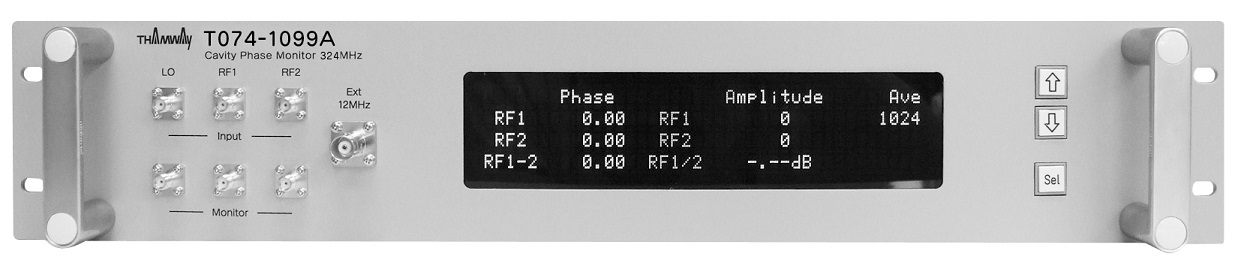
| ■PHASE MONITORING SYSTEM (PHASE COMPARATOR) |
| This is a monitoring apparatus where it measures the phase and amplitude of the two identical frequency signal with high accuracy. The measurement results displayed on the front panel and then output to the higher-level control system. |
| Down converts the monitor signal to an intermediate frequency of 12MHz, and then by acquiring at 48MHz, has obtain the phase information as the I,Q component. It is also possible to monitor simultaneously the amplitude information. |
| ■Features |
|
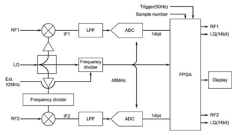
Each RF input signal is needed to be synchronized with a common master clock (synchronized phase). (1) Two measurement signals [RF1], [RF2] and a [LO signal] are inputted. Each inputted signal becomes monitor output. (2) The input LO signal is divided to generate a clock signal of 48MHz, syncronizing with a reference signal of 12MHz [Ext. 12MHz]. Even if the Ext. 12MHz is not inputted, a 48MHz clock signal based on the LO signal is generated, making measurement possible. (3) The frequency of two measured signals is down-converted into an intermediate frequency of 12MHz [IF1] by the LO signal. Alow pass filter makes its harmonic components smaller than -60dBc. (4) The signal to noise ratio (S/N) of the RF signal needs to be larger than 50dB in order for the measurement error to be less than 0.3%. Therefore, an active multiplier is used as a down converter, rather than a passive device mixer. (5) With the oscillation timing of a trigger signal (Max:50Hz) inputted from an external source, a 14bit A/D converter starts to sample the IF1 and IF2 with the 48MHz clock. The IF1 (12MHz) is sampled (A/D conversion) every 90 deg in phase, so that I (or -I) or Q (or -Q) components are averaged, respectively. (6) IF1 and IF2 are sampled (A/D conversion) in a sample length of 2ⁿ (n:0 to 16) that can be set on the front panel. (7) The 14bit I and Q components averaged in (6) (a total of four data sets obtained from both RF1 and RF2) are outputted externally to the timing of the trigger signal. (8) The I and Q components (average) obtained in (6) are converted into phase (0 to 360deg) and amplitude (0 to 8191) components RF1 (IF1) and RF2 (IF), respectively. From these values, the phase difference and the amplitude ratio between RF1 and RF2 are obtained and displayed on the front panel. |
| ■Stable Performance |
|
(1) IF output (including intermediate frequency 12MHz and Low Pass Filter) temperature characteristics of the phase and amplitude are 0.1deg/℃ and 0.1%/℃, respectively. (2) Harmonic components of the intermediate frequency (before A/D conversion) are smaller than -60dBc. (3) Measurement error after averaging of the phase and amplitude are ±0.2deg and ±0.2%, respectively. |
 |
 |
| Model | T074-1099A | ||
| Input signal | |||
| Cavity monitor signal 1 [RF1] | Cavity monitor signal 2 [RF2] | ||
| Frequency | 324MHz | Frequency | 324MHz |
| Input impedance | 50Ω | Input impedance | 50Ω |
| Input level | -10dBm to +20dBm | Input level | -10dBm to +20dBm |
| Input connector | SMA-FEMALE | Input connector | SMA-FEMALE |
| LO signal | Sample trigger | ||
| Frequency | 312MHz | Frequency | 25Hz or 50Hz |
| Input impedance | 50Ω | Input impedance | 50Ω |
| Input level | +10dBm±2dBm | Input level | 5V |
| Input connector | SMA-FEMALE | Input connector | BNC-FEMALE |
| Ext.12MHz | |||
| Frequency | 12MHz | ||
| Input impedance | High Impedance | ||
| Input level | TTL | ||
| Input connector | BNC-FEMALE | ||
| Output signal | |||
| Monitor output of the input/output signal | Measurements VME output | ||
| Output signal | Monitor signal1, 2, LO signal |
Output signal | Each of the monitor signal [I], [Q] component, A/D conversion value 14bit binary |
| Input/Output impedance | 50Ω | Output connector few | 40pinx2 (RF1 and RF2) |
| Output connector | SMA-FEMALE | Output type | Open collector, +24V power supply |
| Output connector | Flat cable connector 40pinx2 (J3432-P302VE equivalent) |
||
| Power supply | AC100V±10% 50/60Hz | ||
| Shape | 19 inches JIS rack case | ||
| Size | 480(W)x88.1(H)x450(D) (mm) | ||